Raphael Fortuna ECE 3400 Wiki
Project maintained by raf269 Hosted on GitHub Pages — Theme by mattgraham
Lab 3
Home
Lab 1
Lab 2
Lab 4
Summary of what was accomplished during the lab
- We used LTSpice to simulate a low pass, high pass, and our microphone high pass filter
- We built a basic microphone circuit and tested it with MATLAB for frequency of 500 hertz using the Nano
- We built the amplifier microphone circuit and tested it again with 500 hertz frequency and used MATLAB and the Nano to analyze frequency
- We implemented a high pass filter and compared the frequency response for a 100-2000 Hz frequency sweep to that of the simulation
- We implemented FFT on the Nano to find frequencies of 500, 700, and 900 hertz
Creating and simulating the LTSpice low pass, high pass and microphone high pass filter
We followed the provided guide in the lab handout in creating a low pass filter using a 33K ohm resistor and .1 micro farad capacitor and looked at the frequency response.
Then we rebuilt it using a 1.2K ohm resistor and .1 micro farad capacitor and measured its frequency response and cutoff frequency by probing Vout.
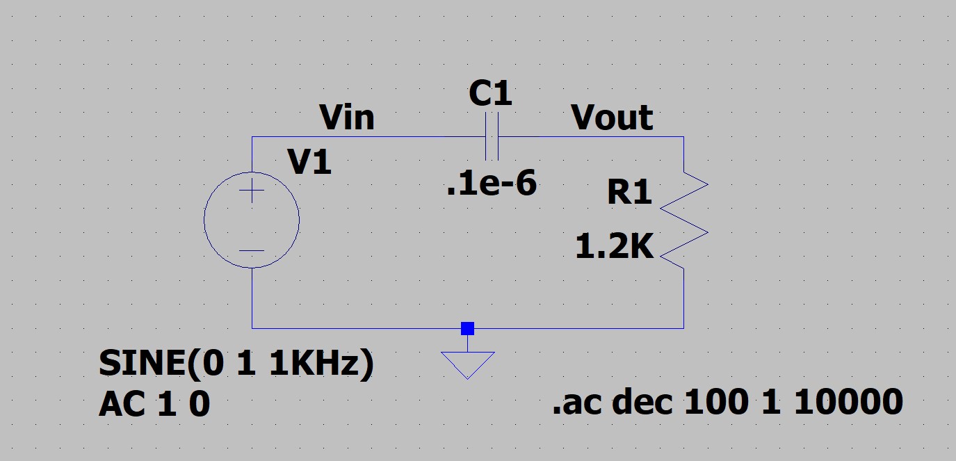
We then created a high pass filter using a 1.2K ohm resistor and .1 micro farad capacitor and measured its frequency response and cutoff frequency by probing Vout.
Here's a picture of our low pass filter graph:
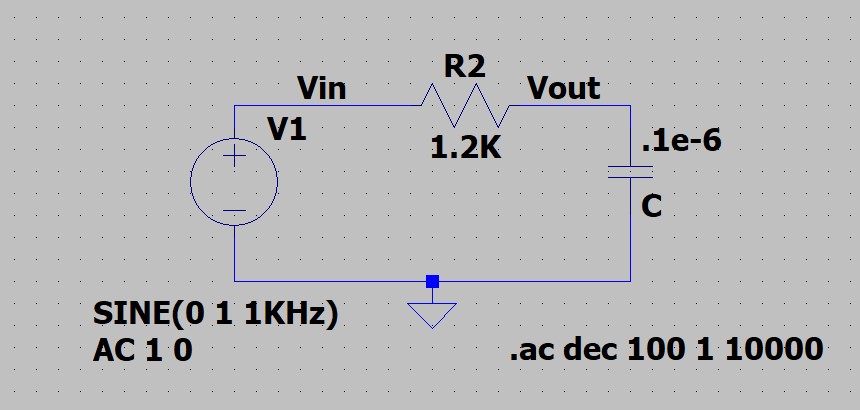
Here's a picture of our high pass filter:
We also went ahead and made the microphone high pass filter to be used later. Below is a picture of it:
Building the basic microphone circuit, implementing ADC0 reading on the Nano, and using MATLAB to perform FFT for a 500 Hz frequency
We first set up the Nano code to be able to read from ADC0 and then output its output to the Serial Monitor to be ingested by MATLAB.
We then set up the MATLAB code to be able to run an FFT on the output coming from the Nano.
Next, we collected the parts needed for the microphone and then built the basic microphone circuit on a another breadboard and then saw that there was a tiny peak at 500 hertz. Here is a picture of it below:

Here is a picture of our microphone circuit:

Building the amplifier microphone circuit and testing it with a 500 Hz frequency
We built the amplifier circuit by collecting all the parts needed using the information from the lecture slides.
We tested the amplifier circuit with the MATLAB code and were able to detect a much higher peak at 500 hertz since the amplifier was able to amplify signal from the tiny microphone.
Here is a picture of our graph:

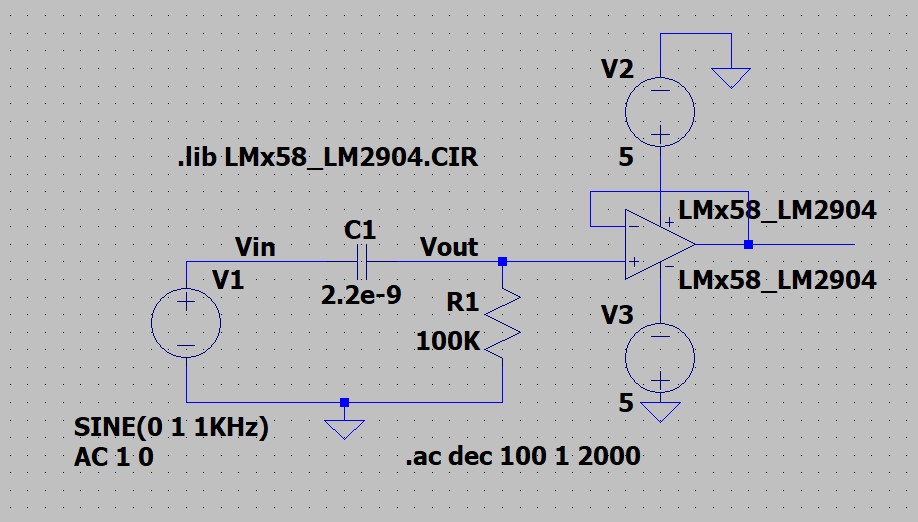
Implementing high pass filter and comparing it to the LTSpice microphone high pass filter
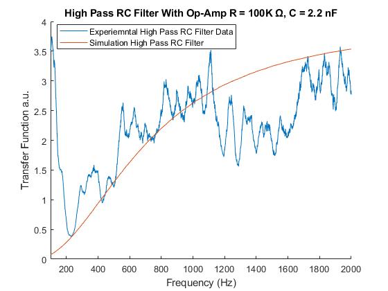
We wanted a cutoff frequency of 723 Hz so we built a high pass filter using a 2.2 pico farad capacitor and a 100k ohm resistor and updated the resistor and capacitor values to our microphone high pass filter in LTSpice.
We then gathered data from the input and output of the high pass filter, smoothed them in MATLAB, and then divided the output by the input to find our frequency response and compared it to the frequency response of that to our microphone high pass filter in LTSpice.
We found that the curve matched pretty well and you can see it below:
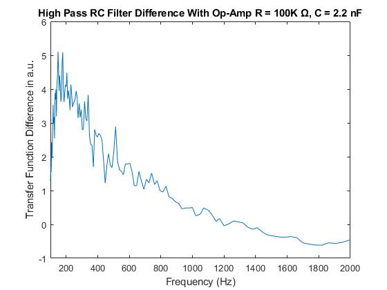
We then also found the difference between the two frequency responses, and you can see our results below:
Here is a picture of our completed filter and amplification circuit:

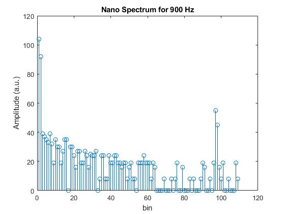
Implementing FFT on the Nano to find frequencies of 500, 700, and 900 Hz
We added and used the FFT library on the Nano to implement FFT on the Nano.
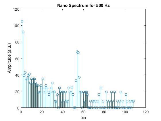
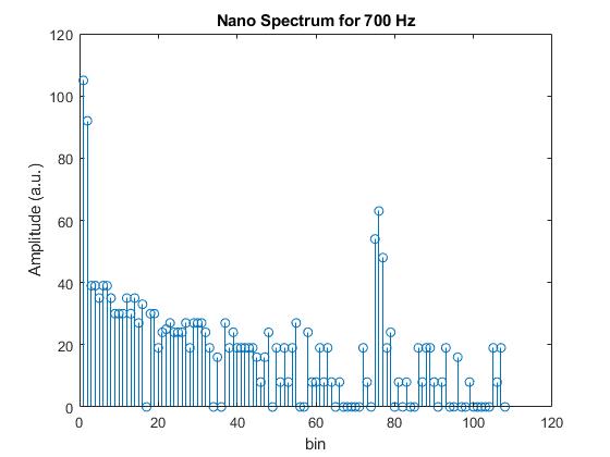
We set up the new Arduino file to run the FFT on the data and then detected the 500, 700, and 900 Hz frequencies using our code with the amplification circuit.
Here our picture of our graphs:
500 Hz:
700 Hz:
900 Hz: